Lathes and Attachments
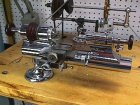
Levin watchmaker's lathe
 `
`
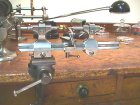
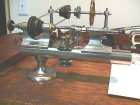
The basic workhorse in my shop. Most watch parts I make are fabricated
on this lathe using one or more of its attachments. This lathe features
precision (class 7) preloaded ball bearings in the headstock. Show here
is the configuration for turning with the slide rest.
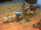
Micro drilling attachment
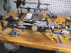
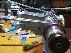
When drilling small holes in the lathe, better concentricity and less
drill breakage can be obtained by turning the drill and the work in opposite
directions.. The big brass handle supplies cutting force like a drill press,
but the actual feed is controlled by a micrometer knob on the right. This
makes it possible to clear out the chips rapidly and resume the cut without
"bumping" the bottom of the hole or suddenly breaking through at the end.
The dial indicator reads the hole depth directly.
The concept of not bumping the hole bottom is important: In steel, any
force applied to the drill while not cutting will burnish and harden the
surface. This effect is quite pronounced in very tiny holes and was a major
problem for the watchmakers in the old days. Modern carbide drills solve
this problem, but they are very brittle and won't stand up to any sudden
loads. Carbide drills are not (to my knowledge) available is sizes less
than 0.004".
Using very small drills in deep holes requires careful attention to
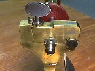
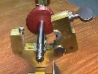
centering. The photo on the right shows the micrometer slides for horizontal
and vertical adjustment of the spindle. A pair of ground WW collet centers
are place in the headstock and drilling spindle. These centers have small
round pins rather than points. Under magnification, the micrometers
are adjusted to bring these pins into alignment.
This is the ultimate tool for repivoting work or any other precision
drilling of small holes. I found this nifty item tossed in a barrel of
old fixtures. The feed handle was broken off but it was otherwise undamaged.
Levin still sells them for the price of a nice used car.
Boley Turns
This is a pair of steel turns from around the turn of the century.
It is illustrated and discussed in Saunier's Watchmakers Handbook.
He shows it set up to be a lathe. Boley made a large number of attachments
for this "prismatic" lathe bed. I have the set of runners for this tool,
but no lathe spindle attachment. Occasionally I use it to finish a staff
between dead centers. A part held between dead centers can be adjusted
to have practically no radial runout. This insures that the part is concentric.
By contrast, a lathe spindle with plain cone bearings must have some radial
clearance to carry the oil film. When loaded during the cut, the spindle
compresses the oil and can make the part slightly elliptical.
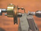
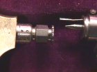
The view on the right shows the turns up close fitted with a brass
driving pulley. The pulley rotates around the fixed center. The pin that
sticks out of the pulley engages a spoke on the watch wheel or a small
carrier attached to the work.
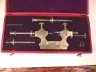
Plain steel turns
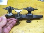
In the good old days, this was the principle tool used by the watchmaker
for fitting and making round parts. The tool is clamped in the bench vise.
The work is held between dead centers and driven with a horsehair bow.
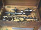
Lorch-Schmidt lathe outfit
Bottum wax lathe
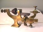
A "wax" lathe is used for turning parts held with a meltable adhesive.
This goop, conventionally called wax or lathe cement is actually more like
violin rosin. Don't be fooled by the primitive look of this tool. It can
support accurate turning that rivals that of most lathes with cone bearings.
This technique has been used to make watches for two hundred years. I frequently
use lathe cement for holding irregular parts or finishing a balance staff.
A glob of cement is inside the hollow spindle which has a recess cut with
an accurate female center. The cement is softened with an alcohol lamp
and the part is inserted. Now for the magic step: the spindle is revolved
while holding a match stick gently against the part. The part will center
itself as the cement hardens and (if done properly) the result is extremely
concentric. Far better than most collets. I am unable to see any runout
(not even vibration) with a Hamilton 0.00005" reading dial gauge.
There are lots of recipes for lathe cement. Some folks even use superglue.
I mix melted flake shellac with a dab of diamond setter's pitch. The pitch
makes the shellac less brittle. I plan to put up a page with recipes for
lathe cement. If you have a good one, please send it and you'll get one
of the credits! Our work might make Yahoo's bizarre web page of the day...
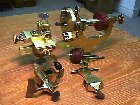
Swiss lathe with mandrill
A Swiss wax-lathe with attachments from the late 19th century. Show
configured as a mandrill on the left and on the right, as a wax lathe.
At about this time, the American WW collet lathes were about to displace
these attractive, but inconvenient "brass engines".
Swiss lathe bearing
The front bearing of the lathe opens to allow rapid replacement of
the whole spindle assembly. In the right hand view, the type-metal insert
can be seen that supports the wax lathe spindle. When used with the larger
mandrill spindle, the insert is removed.
Webster-Whitcomb lathe
The lathe on the bench top shown above is a Webster-Whitcomb. This
pattern, usually nickel plated, dominated watch lathe design for the next
75 years, displacing both the mandrill and the turns as the most important
tool for making and fitting parts.
Actually, since the 1940's, the only tools required by the average watch
repairer were tweezers, screwdrivers, a cleaning machine and a staking
set. The ready availability of interchangeable parts made turning and milling
skills unnecessary. Although present on the bench in most jewelry stores,
the watch lathe was largely an ornament. Today, with the old factory stocks
finally depleted, fine antique watches and clocks must once again be maintained
by creating new parts from raw materials.
Boley F1 lathe
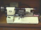
This machine is one of the few modernized versions of the watchmakers
lathe. Between 1900 and 1970, watchmaker's lathes all looked pretty much
like the Webster-Whitcomb shown in the previous section. The F1 is (was?)
one of the last designs from the now moribund Boley company, dating from
the late 1960's to early 1970s. (Can someone help me date this thing?)
One of its unusual features is that the operator may sit at the tailstock
end looking into the headstock. A hand rest on the right (behind in this
view) supports the right wrist holding the graver on the t-rest, also placed
on the right side. The headstock end has a prop that tilts the whole
bed toward the operator. In addition, the entire bed rotates along the
axis to present a comfortable view. The lathe is ideal for pivoting work
in this orientation.
The left side (or front as shown here) has a lever that operates an
indirect friction drive to a concentric "throw" wheel. The work is held
between micro dead centers. A carrier attached to the work is driven by
a pin that extends from the throw wheel. This is essentially a modern version
of the antique turns discussed above. The dead centers insure absolute
concentricity. The friction drive allows the operator to limit the force
applied to the work. If the graver catches in the work, the throw
wheel will simply stop. Sometimes.
This was my first watch lathe given to me by my wife many years ago.
She was quite supportive back before my hobby got completely out of control.
To get even, she is now devoted to horsing. It worked.
Pivot drilling lathe
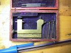
When a pivot is broken off, this tool can be used to redrill the arbor
so a new one can be pressed into place. Pivots can be as small as 0.004",
so this takes some care. To make matters worse, the arbors are commonly
hardened. The work is held between centers and driven with a bow as in
the turns. The center on the right side is hollow. On the far right side
of the case are two small runners that hold the drill. The drill
is inserted through the hollow center and pressed against the work while
the bow drives it back and forth. The drill is sharpened so it cuts in
both directions.
Jacot tool
The Jacot tool is special purpose dead center lathe. It is used to
burnish and adjust the size of cone pivots, most frequently on the balance
staff. The balance wheel and staff assembly are placed on the tool with
one pivot in the female center and the other resting in a groove. The balance
is rotated back and forth with a horsehair bow while a burnishing file
presses the pivot into the groove. The result is a concentric pivot with
a burnished finish. Each of the extra runners has a series
of graduated grooves cut on one end. A small gage is included for measuring
the pivots.

 `
` `
`

