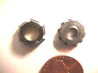

I have found that fly cutters give a better finish on brass wheels because it is possible to give the cutter both radial relief and edge clearance. The multitooth cutters shown above have no edge clearance at all. This is what makes it possible to sharpen them over and over without altering the profile. This is important for quantity production. The big problem for one-off gears is the time required to make them as well as the difficulty of driving them with no wobble or radial run out. The smallest error will make the side of the cutter rub against the brass, spoiling the finish and turning up a big burr on the tooth.
Learning how to make them is necessary, however, because they're required
to cut steel pinions.
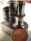
This is a side view of the form tool holder I use for making gear cutters.
The actual form is a piece of high speed steel drill rod. (I use broken drill
bits when possible.) The diameter of the rod determines the profile of the
tooth addendum. The segment of rod is soft soldered to a notch in the brass
carrier.
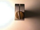
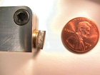
This end view shows the brass carrier with the drill rod soldered in place. It is slightly tilted to give clearance to the cutting edge. Both ends of the rod are sharpened so it can be rotated 180 degrees to form each side of the gear cutter tooth profile.
After much travail, I decided to try a variant of the bent-tooth method. The process as described in Levin's Practical Benchwork for Horologists seemed the most feasible. Saunier and many other books recommend simply bending the cutter teeth back, but I found this technique impossible to control. Higgenbothem's Precision Time Measures suggests using a set of tiny wedges to bend the teeth. I found this process equally exasperating and ended up with teeth bent in all directions. The following sections show the method I use now.
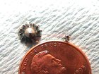
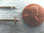
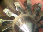
The cutters are turned up as disks in the lathe using a form tool as described in the sections below that show how to make a fly cutter. Because the cutter is less than 1/4 inch in diameter, I turn it out of the solid with the 1/8 inch shaft in place. After turning, a ring of holes is drilled along the edge as shown in the magnified view. The teeth are then separated with finely ground slots. I use a 0.005 silicon-carbide Damascus separating disk to make the slots because they generate less burr on the exit side of the cut. Two cuts are made per slot: one tangent to the hold and one to remove the pie-shaped slice as shown in the photo. The radial relief is then created by driving a hardened, polished taper pin into the holes. I use fine sewing needles for this process. This bends the tooth back by an exactly controllable amount. The holes are drilled just under the largest diameter on the needle. The difference in size between the needle and the hole determines how much the tooth will be bent.
To support the cutter when bending the teeth, I use a large block of steel with a hole for the cutter shaft. The cutter is placed in the hole so the disk is supported by the block. A parallel hole is drilled to clear the needle when pressed through. By using this block, the teeth are supported so they aren't bent out of the cutting plane. The needle is held in the chuck of a drill press. The quill is fed down to drive in the needle, which is now firmly stuck in the cutter. To withdraw the needle without bending the teeth upward, I use a brass bar with a slot that just clears the needle. I press this tool down on the cutter by hand while raising the drill press handle. A more elaborate jig would make the process easier.
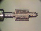
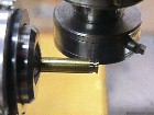
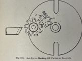
Currently, I use circular cutters for pinions. I'd like to investigate making really tiny fly cutters for pinions as well. The problem is keep the net diameter really small and still have enough mass in the cutter. A miniature version of the circular rod cutter shown would probably not work for steel pinions.

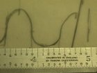
Magnified 100 times, a pair of teeth are traced on acetate. This gear is part of the canon pinion in a quartz chronograph. The teeth have involute profiles because the wheel is driven by a pinion. (Epicycloidal gearing is used in watch trains, but it doesn't work well when pinions with few teeth have to drive a gear wheel.) Modifed epicycloidal profiles are sometimes used in this situation, but modern watches used hobbed brass (or in this case molded plastic) involute gears. (See Davis, Gears for Small Mechanisms for additional information on gear geometry.)
For an original watch, the computer can laser print the software-generated tooth profile on overhead transparency film.
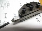
The form tool will be used to cut the fly cutter. It starts out life as an ordinary slide rest tool for the lateh carefully sharpened to a polished point.

The form tool blank is placed on the stage of the shadow graph with the tracing of the tooth taped to the screen. A diamond hone is used to round off the tip of the form tool while watching the shadow of the tool tip projected on the tracing. It takes less than 3 minutes to shape the required addendum curve. Shown here is the finished tip profile offset slightly so you can see the pencil tracing as well. This wheel has involute teeth.
The three views above show the parts of the fly cutter. (The 8mm collet stem is standing in a drill bushing.) The center view shows the cutter in the off-radial position for turning the profile. The view on the right shows the cutter in position for forming a gear tooth. You can see in the right view how the cutter has radial relief, while in the center view, the profile is concentric with the disk.
To make the clamping disks: First form the disks to fit the collet arbor.
The disks are clamped together with a large washer and screw shown on the
desktop in the left most view. When drilling the holes for the cutter, assemble
the two disks with a sheet of paper between them. Drill the holes for a snug
fit. When assembled without the paper, the cutter will be tightly clamped
in place.
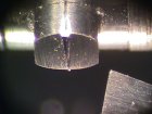
When forming the cutter as shown above, the arbor is held in the lathe with the form tool in the slide rest. The form tool is tilted so the left edge is parallel to one edge of the cutter tooth. For this gear, about 10 degrees. The radius we shaped on the form tool tip will form the addendum curve at the root of the cutter. (Which will form the addendum profile of the gear tooth tip.)
The fly cutter blank has a scratch mark visible on the top edge. This is alligned with the split between the two clamping disks. To give the cutter side clearance, the fly cutter is rotated about 2 degrees counter-clockwise when forming the right side as shown above. To form the other side of the fly cutter, the pair of disks with the cutter still held between them in the hole is removed from the arbor, turned around and reattached. Now the cutter will be inverted. It is then rotated 4 degrees clockwise so the other edge will have edge clearance of 2 degrees.
As shown in the photo above, both sides have been turned to shape. The amount the form tool is feed in laterally to leave the cutter as shown is calculated to leave the cutting tooth in the middle of the blank. The fly cutter tooth is much too wide at the top end at this point. It tapers down to nothing at the bottom end: The right width is somewhere between.
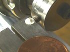
After cleaning off the Casenit, I polish the cutting edge by hand with bits of Cratex wheel. If you are brave, you can try jewelers's rouge on a soft buff held in the flexible shaft tool. I found this process uncontrollable. It's too easy to reshape such a tiny cutter.
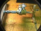
The fly cutter is placed in a pin vise which is in turn clamped in an old graver sharping holder. (It looks like a brass Crocker graver sharpener.) You might prefer to use your trusty Holtzapffel goniostat instead. The cutter itself rests on a diamond grinding plate.
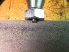
The above view shows the fly cutter resting on the diamond plate being ground.
The nut protects the pin vice from damage. About half the cutter has been
ground away. We keep grinding and comparing the cutter profile to the tooth
space of the gear. You can try the fit of the cutter in a tooth space
under magnification without removing it from the pin vise-jig assembly.
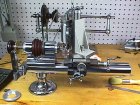
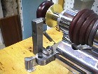
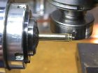
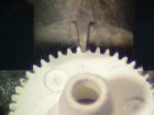
The wheel blank is turned to the computed or measured outside diameter and left in position for cutting the teeth. The milling spindle holds the fly cutter arbor as shown. An indexing plate is attached to the spindle to space the teeth. It is important to mount the index plate before turning the gear so the blank will not be disturbed after turning. (I forgot this time and had to turn another blank.) The photo below shows the gear after all the teeth are cut.
Avoiding or removing burrs from very fine pitched gears is a difficult problem. In this case, the gear blank and hour hand post were formed in one piece on the end of a brass rod. The wheel thickness was defined by partially cutting off the wheel. After cutting the wheel teeth, the parting tool is again advanced into the groove without touching the back side of the gear. If the parting tool is sharp and has adequate side clearance, the burrs are sheared off without being forced between the finished teeth.
The inside bore and outside taper for the hour hand are done while the blank is still in the lathe. This wheel required a two-step bore, so it had to be reversed and centered on a cement chuck to enlarge the hole on the back side. Above is shown the result after these steps.
This view shows the wheel in place with the hour hand mounted.
The above view is a close-up showing the mesh with the drive pinion. To finish, the teeth are first gently polished by hand with a piece of artist's vine charcoal. The wheel is then mounted on a tapered mandrel in the lathe and polished with shaped fragments of wet Water-of-Ayr stone.
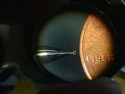
Ward Goodrich in his mostly-great book The Watchmaker's Lathe suggests turning the cutters from disks and then charging them with diamond dust. This sounds like a good idea but how could it be done? The tool for forcing the diamond powder into the cutter would have to have a radius smaller than the addendum curve for the gear. The cutter would have to be made out of a material softer than the brass gear or the diamond dust would migrate into the brass gear turning it into a cutter for the watch pinion.
I did several experiments using copper disks. I tried to charge the formed edges with diamond paste using a ball point pen. The balls are made of irridium, which should be hard enough to force the diamonds into the copper. I got very poor results because I couldn't get the diamonds to stick to the copper without using excessive pressure that distorted the tooth-space form.
Any method that would put a uniform rough surface on a steel cutter would be worth a try. The great appeal of this method is that the finish and concentricity of the brass gears would be better. When using regular cutters, the gear must be formed on the end of a bar or clamped/soldered to a holder. After the teeth are cut, the actual arbor for the watch is fitted. Some error is bound to occur. Regular cutters also produce cutting marks that are at right angles to the sliding action of the gear when meshed with the pinion. (Some sliding is bound to occur due to the approximations used in forming the teeth. Small pinions with few teeth cannot have perfect rolling action with epicycloidal wheel teeth even in theory. In practice, the profiles for all gears are compromised by design to accomidate reasonable manfacturing tolerences for depthing errors.
Rounding up with a grinding cutter would help with both of these problems
because the wheel teeth would
first be cut with a simple saw. Then the wheel is mounted on its own arbor
and rounded up between centers. The result will be very a very concentric
wheel. If the rounding cutters have a grinding rather than cutting action,
the finish should be quite good as well.
It would be interesting to know how 3M Company makes their inexpensive diamond wheels. They look like they were sprinkled with diamonds and then dipped in molten solder. The diamonds are, in effect, plated onto the wheel. Diamonds could be dusted onto the wheel and vaporized metal sputtered on in a vacuum. I think it would take quite a while to put down enough to make the diamonds stick. Even the commerial wheels shed some diamond power in use, so I just can't see how to make this idea work.
An abrasive that won't charge brass or a way to roughen a hardened steel disk with the tooth space profile turned on the edge seem the most promising directions. Any ideas?
Reviews for English language watchmaking books
with special emphisis on wheel cutting will appear here soon. Stay tuned.